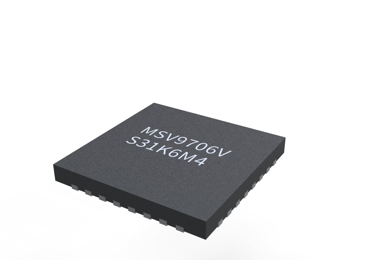
MSV9706 — MEMS Vision Controller
The MSV9706 is a high-performance MEMS Vision Controller designed for precise reflectance and motion sensing. It integrates MEMS driver, TIA, ADC, and noise cancellation to enable compact and reliable embedded vision solutions.
Description
MSV9706V integrates a two-axis MEMS driver, vision timing control, Transimpedance Amplifier (TIA), and on-chip ADC with a built-in noise-cancellation algorithm. It outputs vision data for near-field reflectance sensing and finger-posture applications, with a primary SPI host interface and auxiliary I²C bus support in the MSV970x platform.
Integrated Signal Chain
Timing control + TIA + ADC on-chip for compact optics and stable SNR in soiling/proximity use cases.
2-Axis MEMS Drive
XP/XN, YP/YN outputs for scanning control and flexible resolution/direction settings.
Host Connectivity
SPI up to 12 MHz with command framing; data-ready via nBRDY; reset via nRST.
Key references: integrated MEMS driver/TIA/ADC and noise cancellation; SPI host interface and I²C support; data ready (nBRDY) and reset (nRST) behavior. :contentReference[oaicite:1]{index=1}
Applications
Targeted for HandiMote finger detection, lens-less/near-field vision sensing, and soiling detection in ADAS and smart headlight systems. :contentReference[oaicite:2]{index=2}
HandiMote Finger Posture
Combine palm 6DoF motion (optional) with MEMS vision for fine posture recognition in HMI wearables.
ADAS / Smart Headlight Soiling
Under-glass reflectance to detect dust or stains affecting sensors/optics; triggers cleaning/alerts.
Lens-less Surface Sensing
Compact optical path that reduces alignment complexity for embedded panels and appliances.
System Block Diagram
Typical integration with Host MCU via SPI; MEMS drivers (X/Y), emitter control, photodetector front-end (PGA/TIA/ADC), and status/interrupt pins. :contentReference[oaicite:3]{index=3}
Host Interface (SPI)
Clock up to 12 MHz; command packet = CMD (e.g., 0x51 read / 0x61 write / 0xAA block) + Sub-CMD + Addr;
monitor nBRDY for data ready. :contentReference[oaicite:4]{index=4}
Reset & Ready
Power-on reset on VPOR; host can pulse nRST; device releases nBRDY after init (~TInit). :contentReference[oaicite:5]{index=5}
Registers
CHIPID=0x9706; status bits include RUN, DIR, EFlag; configuration covers resolution/direction,
ADC averaging (2–5×), emitter drive (OD/PP) & polarity, MEMS latency bias/multiply, PD bias/gain/exposure. :contentReference[oaicite:6]{index=6}
Key Pins
32-pin assignment highlights(UFQFPN32, 0.5 mm pitch)— see full table in datasheet. :contentReference[oaicite:7]{index=7}
- SPI:
CS,CLK,MISO,MOSI - Status/Reset:
nBRDY(busy/ready),nRST - MEMS Drivers:
MEMS XP/XN,MEMS YP/YN - Emitter:
EMIT C(DAC out),EMIT Ctr(OD/PP) - PD Front-End:
ANA INP/INN,TIAOP,TIA INN,PGA VINP/OUT - Motion Sensor Aux:
MOT SDA/SCL,MOT nRST,MOT GINT - Power/Ground:
VDD,VDDA,VSS,VSSA
Quick Specs
SPI (≤ 12 MHz); I²C bus support in platform
Resolution/direction select; ADC averaging 2–5×; emitter OD/PP + polarity
Bias selectable (100–1400 mV); Gain ×1/×2/×4/×8; Exposure 3/6/10/15 µs
POR +
nRST; nBRDY indicates ready/data0x9706
Timing/commands, register map, and PD/ADC settings per official datasheet. :contentReference[oaicite:8]{index=8}
Package Information
UFQFPN32, 5 × 5 mm body, 0.5 mm pitch; exposed pad on underside recommended to be tied to PCB ground.
| Package | Pin Count | Pitch | Body Size (mm) | Notes |
|---|---|---|---|---|
| UFQFPN | 32 | 0.5 | 5.0 × 5.0 (typ) | Exposed pad to GND; follow recommended footprint |


Request Full Documents
For complete electrical characteristics, SPI AC timing, register details, and reference designs, contact our product team.
Provide your company, project overview, and expected MP schedule for faster NDA processing.
